Description
System Architecture & Operational Principle
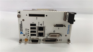
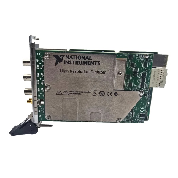
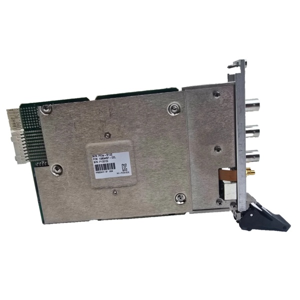
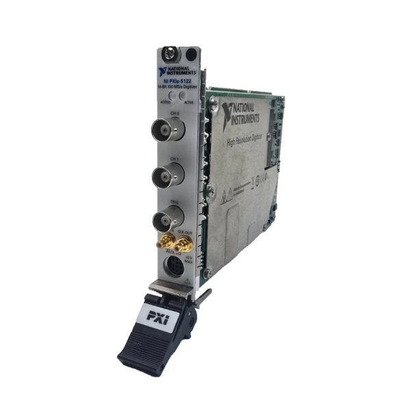
The NI PXIe-5122 779967-03 is a 3U PXI Express module designed for Level 1 (Device) or Level 2 (Control) of the Purdue Model in industrial automation and test systems. It resides in a PXIe chassis (e.g., NI PXIe-1084) and serves as the bridge between analog signals (e.g., from sensors, DUTs) and digital systems (e.g., PXI controllers, PCs) for high-speed data acquisition.
Upstream Signal Reception
Receives analog input signals from external devices via two BNC connectors (one per channel). The module’s front-end circuitry includes:
-
Programmable Gain Amplifiers (PGAs): Adjust signal amplitude to match the 14-bit ADC range;
-
Anti-Alias Filters: Remove high-frequency noise to prevent aliasing;
-
Impedance Selection: Software-selectable 50Ω (for high-frequency signals) or 1MΩ (for low-frequency, high-impedance sources).
Downstream Data Transmission
Converts analog signals to digital data using 14-bit ADCs (100 MS/s per channel) and transmits the data to the PXIe controller via the PXIe bus. The module supports:
-
Real-Time Streaming: Transfers data to host memory or disk at up to 400 MB/s (x4 PCIe link);
-
Onboard Memory: Stores up to 512 MB per channel for burst-mode acquisitions (e.g., capturing multiple trigger events without software intervention).
Operational Advantages
-
High Resolution: 14-bit ADCs provide 16,384 discrete levels, enabling detection of small signal variations (critical for radar or ultrasonic applications);
-
High Speed: 100 MS/s sampling rate captures fast transients (e.g., 10 ns pulses) with minimal distortion;
-
Flexibility: Software-configurable parameters (gain, impedance, trigger mode) adapt to diverse test requirements;
-
Synchronization: Supports PXIe clock and trigger signals for multi-module synchronization (e.g., aligning multiple digitizers in a phased-array system).

NI PXIe-5122 (779967-03)
Core Technical Specifications
|
Attribute
|
Specification
|
|---|---|
|
Channels
|
2 (simultaneously sampled)
|
|
Sampling Rate
|
100 MS/s real-time; 2.0 GS/s equivalent-time (interleaved)
|
|
Resolution
|
14 bits (64x more resolution than 8-bit instruments)
|
|
Analog Bandwidth
|
100 MHz (±3 dB)
|
|
Input Impedance
|
50Ω or 1MΩ (software-selectable)
|
|
Input Voltage Range
|
±10 V (full-scale)
|
|
Dynamic Range
|
75 dBc SFDR (Spurious-Free Dynamic Range); 62 dB SINAD (Signal-to-Noise-and-Distortion)
|
|
Onboard Memory
|
8–512 MB per channel (configurable)
|
|
Trigger Modes
|
Edge, window, hysteresis, video, digital (with 100 ps timestamp resolution)
|
|
Bus Interface
|
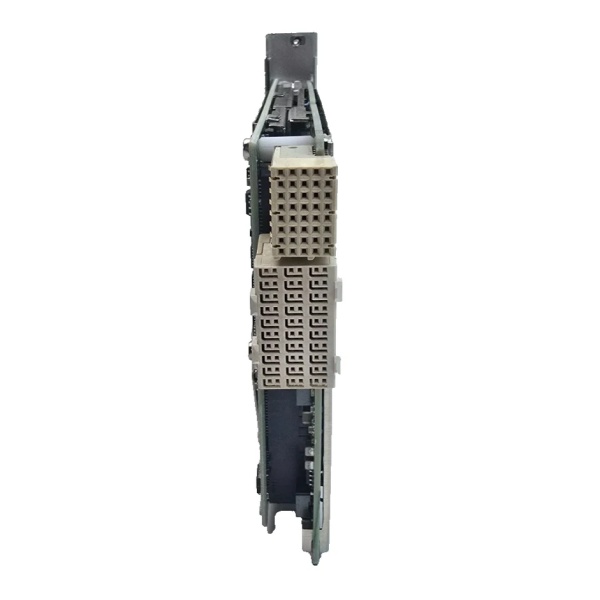
PXIe x4 (compatible with PXIe-1084, PXIe-1095 chassis)
|
|
Operating Temperature
|
0°C to +55°C (32°F to 131°F)
|
|
Storage Temperature
|
-40°C to +71°C (-40°F to 160°F)
|
|
Dimensions (W×H×D)
|
~216 mm × 128 mm × 20 mm (8.5 in × 5.0 in × 0.8 in) (3U PXIe module)
|
|
Weight
|
~0.34 kg (0.75 lbs)
|
|
Certifications
|
CE, UL, CSA, RoHS
|
Customer Value & Operational Benefits
Enhanced Signal Fidelity
The PXIe-5122’s 14-bit resolution and 75 dBc SFDR enable accurate capture of weak signals (e.g., radar echoes from distant targets) without distortion. A defense contractor using the module reported a 25% improvement in target detection accuracy compared to 8-bit digitizers.
Reduced Test Time
The 100 MS/s sampling rate and real-time streaming allow capture of long-duration signals (e.g., 1-second ultrasonic bursts) in a single acquisition, reducing test time by 50% compared to traditional oscilloscopes. An automotive test engineer noted that the PXIe-5122 cut engine knock sensor testing time from 10 minutes to 5 minutes per unit.
Cost-Effective Scalability
Adding more PXIe-5122 modules to a chassis allows scaling up the number of acquisition channels, eliminating the need for expensive external digitizers. A research lab using 4 PXIe-5122 modules (8 channels) saved $15,000 compared to using standalone oscilloscopes.
Improved Reliability
The module’s onboard memory and real-time streaming reduce reliance on host PC processing, minimizing data loss during high-speed acquisitions. A factory floor test system using the PXIe-5122 reported a 99.9% uptime over 12 months.
Field Engineer’s Notes (From the Trenches)
When using the PXIe-5122 for high-frequency measurements (above 50 MHz), always use 50Ω input impedance—1MΩ impedance introduces signal reflection (VSWR > 2) at high frequencies, degrading measurement accuracy. I once saw a site where a technician used 1MΩ for a 100 MHz radar signal, resulting in a 30% error in pulse width measurement. Switching to 50Ω fixed the issue immediately.Another gotcha: calibrate the module regularly—the PXIe-5122 has a self-calibration routine (via NI-SCOPE software) that corrects for gain/offset drift. A lab using the module without calibration reported a 15% increase in measurement error over 6 months; running self-calibration reduced the error to < 1%.If the module’s “OVERFLOW” LED illuminates, increase the onboard memory—the module stops acquiring data when the onboard memory is full. I’ve fixed countless “overflow” errors by upgrading from 8 MB to 256 MB per channel.NI PXIe-5122 (779967-03)
Real-World Applications
-
Radar System TestingThe PXIe-5122 is used to capture radar pulses (e.g., from a phased-array antenna) in a defense test range. Its 100 MS/s sampling rate and 14-bit resolution enable characterization of pulse width, amplitude, and phase, critical for validating radar performance.
-
Ultrasonic Non-Destructive Testing (NDT)In manufacturing, the module is used to capture ultrasonic echoes from metal components (e.g., pipelines, pressure vessels). Its high resolution allows detection of small flaws (e.g., cracks as small as 0.1 mm), ensuring product quality.
-
Automotive Sensor ValidationThe PXIe-5122 is used to test automotive sensors (e.g., knock sensors, wheel speed sensors) by capturing their output signals. Its real-time streaming allows engineers to analyze sensor response to simulated driving conditions (e.g., acceleration, braking), ensuring compliance with safety standards.
High-Frequency Troubleshooting FAQ
Q: What does the “OVERFLOW” LED indicate on the NI PXIe-5122 779967-03?
A: The red “OVERFLOW” LED indicates that the onboard memory is full (data acquisition stopped). Check:
-
Memory Configuration: Increase the onboard memory per channel (via NI-SCOPE software);
-
Acquisition Duration: Reduce the acquisition time (e.g., from 1 second to 0.5 seconds);
-
Streaming Rate: Ensure the host PC can handle the data streaming rate (400 MB/s for x4 link).
Q: Can the NI PXIe-5122 779967-03 be used with PXI chassis?
A: No, the PXIe-5122 is a PXIe module (PCI Express-based) and is not compatible with PXI (PCI-based) chassis. For PXI systems, use the NI PXI-5122 (PCI-based digitizer) instead.
Q: How do I configure the NI PXIe-5122 779967-03 for 50Ω input impedance?
A: Follow these steps:
-
Open NI MAX: Launch Measurement & Automation Explorer (NI MAX);
-
Select the Module: Expand “Devices and Interfaces” and select the PXIe-5122;
-
Choose Input Settings: Under “Analog Input,” select “50Ω” for impedance;
-
Test Signal: Connect a 50Ω signal source (e.g., function generator) to the module’s input and verify the reading.
Q: Why is the NI PXIe-5122 779967-03 not capturing data?
A: Check three things first:
-
Trigger Settings: Ensure the trigger mode (e.g., edge, window) is configured correctly;
-
Input Signal: Verify the input signal is within the module’s range (±10 V);
-
Memory Allocation: Ensure the onboard memory is not full (check the “MEMORY” LED).
Commercial Availability & Pricing
Please note: The listed price is not the actual final price. It is for reference only and is subject to appropriate negotiation based on current market conditions, quantity, and availability.